Design of the V1 Spectrometer
Several aspects need to be considered when designing the spectrometer: where and how to impact the magnetic field, where to locate the position detectors, which solution to use for the detectors and how to implement the readout electronics. Each point is detailed here
Geometry of magnet and detectors
The shape of the magnetic field and the location of the position detectors are dictated by the need to minimize the resolution on the momentum for a fixed resolution on the position coordinate. While the optimal dispersion can be achieved by positioning the detectors as far as possible, this is not necessarily the optimal criterium. The momentum resolution is in fact dominated by the angular dispersion which overlays in a given position trajectories from significantly different momenta. This component of the error can be shrunk if there exist focii of the trajectories, i.e. points where all trajectories of a given momentum converge regardless of the angle at the origin. It has been studied that for uniform magnetic fields as we are currently investigating, this can be achieved if the magnetic field is not null in regions elongated along the direction of the impacting beam.
The reference system is defined below: the point (0,0,0) corresponds to the center of the magnet.
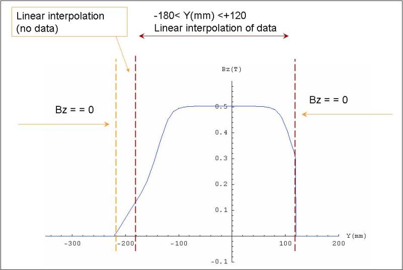
Above is also shown the measured Magnetic field Bz (z direction) as a function of the applied current I. We have data of the measured Bz when the current is set to 20A, 50A and the nominal value of 100A. In each of this three datasets the Bz is measured at z=+-10 mm, z=+-5mm and z=0. For a fixed z steps in y direction are regularly taken every 10 mm from y=-180mm to y=120mm: in x directions Bz was measured from x=-500mm (starting with a step of 20 mm) to x=500mm with a fine step of 5 mm where the field is higher.
In order to obtain a continuous curve for Bz linear interpolation was done where no data were available. The situation is well summarized here below.
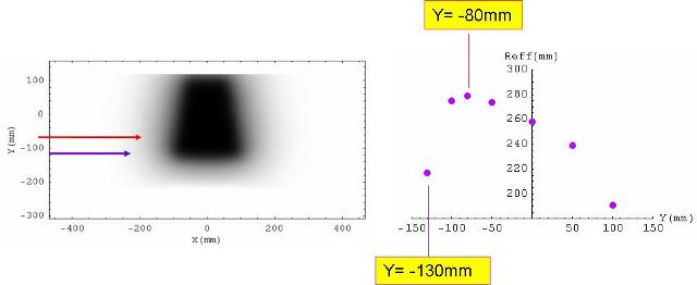
In order to measure energies over a broad range we have to maximize the deflection of the beam. The magnetic field is not negligible even outside the dipole region. For this reason, a useful quantity to study the beam deflection is given by Reff(y)=∫dx Bz(x,y,0)/Bz(0,0,0). In the following plot we see that maximum deflection can be obtained by positioning the beam at y=-80mm.
Nonetheless, this is not the best configuration for our problem. In fact the initial electron beam will have an intrinsic unavoidable angular divergence. Simulations estimate this angular divergence of about 2mrad. We have studied that if the electron beam is sent along the fringe of the magnet trajectories of the same energies with different initial directions will focus. The optimum position for the detector is given by the curve drown by the focii. We have also observed that focii position, where focii exist, is independent of the initial divergence.
During the first phase of the experiment two detectors will be used: a low detector will collect electrons from 20 to 180 MeV while electrons with energy above 180MeV and the laser beam itself will impact on the high detector. The position of the low detector is given by the position of the focii of the trajectories.
Given the shape and intensity of the magnetic field, the magnet used for Prototype V1 is not able to focus energies above 180MeV. For this reason the high detector is located as far as possible (perpendicular to the laser beam direction at a distance of 70cm from the center of the magnet), so to increase the deflection for different energies.
Design of the Position Detector
Usually in Laser Plasma Acceleration experiments optical devices are used to analyze the electron energy spectrum, in particular positions are measured by LANEX films read by CCD cameras. In this case there are several disadvantages of such a solution:
- the large size of the magnet makes it difficult to tune the optical setup for such a detector
- syncrotron radiation photons are also detected and risk to bias the charged particle spectra
- the large energies reached by the accelerated particles risk to saturate the device
Among the non-optical devices, we had to choose a detector that could operate in vacuum, tolerate a large number of impacting particles and be of limited cost. We therefore chose to use scintillating fibers
Read Out
The readout is made with MAROC chips as integrated by the Istituto Superiore della Sanita' (Evaristo Cisbani and collaborators). A test stand for the electronics has been setup in the LAB at "La Sapienza"[e-log]].
To reduce the impact of noise, an attenuator has been positioned between the SamTec cable and the MAROC. Details in the "Technical Instructions" section below.
Expected resolution
Once specified the detector position we can evaluate the different sources of uncertainty on energy reconstruction. Two mainly sources have to be considered:
- the intrinsic detector resolution caused by the physical dimension of the fibers (1mm of diameter);
- the angular divergence.
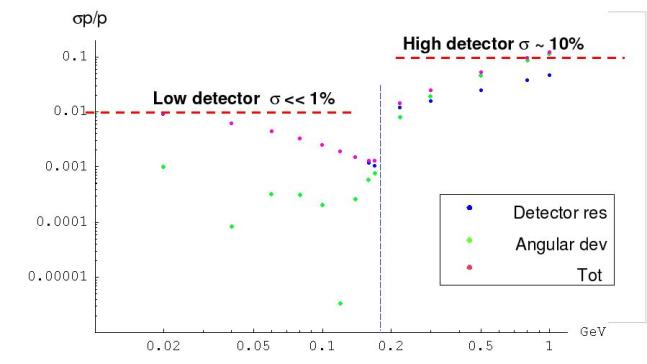
Here below are plotted the two contributions separately and also the sum squared resolution as a function of the beam energy. The resolution is estimated as σp = dp/dx σx. σx is related to the diameter of the fiber when detector resolution is studied. We have to consider as σx half of the distance between two trajectories of the same energy, one generated with a positive angle the other one with a negative angle with respect to the laser beam direction, in order to have 2 mrad of angular divergence between the two trajectories.
Performances between low and high detector will be different mainly because of the angular effect for the high energies.
The pointing instability of the laser was also studied and our results show that the situation shown above is not significantly different even if these effects are of the order of degree. First we show the resolution for the low detector as a function on the detector coordinate x (x=0 represents the first fiber)
while the following plots show how resolution changes if different errors occur.
A misalignment of the different devices of the order of mm leads to a the following resolutions:
We can conclude that with the Prototype V1 it is possible to measure energies up to 200MeV with a very good resolution less then 1% and the resolution remains less then 5% up till energies of 500Mev.
Techincal instructions
Specs of the Dipole: specsofdipole.pdf
Specs of the detector: specifichejul09.pdf
Geometry of alignment: Disegno finale
Electronics design: MAROC datasheet and attenuator simulation


