Table of Contents
Spectrometer
[N. Drenska, R.Faccini, P. Valente ("Sapienza" Universita' and INFN Rome), C. Gatti [LNF], S. Martellotti (Universita' Romatre of Rome)]
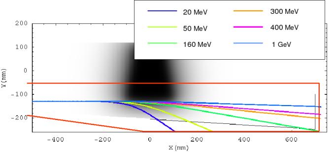
The increase in the energy of the accelerated particles opens the field to high-energy specific diagnostic detectors. In particular the experiment will also be equipped with a magnetic spectrometer. The principle of work is simple: the accelerated charged particles (electrons or ions) will traverse a region where a magnetic field is present and will therefore have a momentum-dependent trajectory. The measurements of the position of such particles on appropriately shaped detectors allows the measurement of the momentum, as described in the following figure:
Working principle of the first version of the spectrometer, top view. The black area represets the area with magnetic field directed orthogonally to the picture, its intensity being proportional to that of the field itself. Coloured lines represent the trajectories of the particles for different momenta and the black lines are the locations of the position detectors, the red straight lines are the contour of the vacuum chamber.
From the high-energy point of view, this detector represents a challenge because the requirements are unprecedented for the field: it must be designed to measure the momentum spectrum of tens of millions of particles arriving simultaneously spread over three order of magnitudes in momentum (10 MeV to 10 GeV). Furthermore the bunch comes from a divergence of few mrad, from a point-like spot located more than a meter before the region with magnetic field. Finally, due to the possible low energy of the particles of interest, the beam needs to be kept in vacuum. The choise therefore falls on electromagnets with a vacuum pipe within the gap.
The work on the topic started in early 2009. Given the need to have a working setup by the end of 2009, a first version of the detector made mostly of spares has been designed. This version, which, as it will be shown is not optimal for the application it applies to, is called Prototype-V1. The final goal is instead to design a customed device with new components.
The V1 Prototype
The need to build a first working device in short terms forced us to use spares of past experiments. The V1 Prototype is made of a magnet spare from LISA, scintillating fibers from NA62 and electronics borrowed by the Instituto Superiore di Sanita' of Rome. The design had also to cope with stringent space constraints, as the room allocated to the diagnostics was fixed before the activity started.
The V0 Prototype
In order to test the response of both the detector V1 and the readout electronics a first Prototype is realized using 64 fibres. These 64 channels are connected to a single PhotoMultiplier H7546 from Hamamatsu. Signals are trasmitted to the readout chip Maroc2.

